|
SUN TRACKER'S WINGS
|
||||||||||||||||||||||||||||||||||||||||||||||||||||||||||||||||||||||||||||||||||||||||||||||||||||||||||||||||||||||||||||||||||||||||||||||||||||||||||||||||||||||||||||||||||||||||||||||||||||||||||||||||||||||||||||||||||||||||||||||||||||||||||||||||||||||||||||||||||||||||||||||||||||||||||||||||||||||||||||||||||||||||||||||||||||||||||||||||||||||||||||||||||||||||||||||||||||||||||||||||||||||||||||||||||||||||||||||||||||||||||||||||||||||||||||||||||||||||||||||||||||||||||||||||||||||||||||||||||||||||||||||||||||||||||||||||||||||||||||||||||||||||||||||||
|
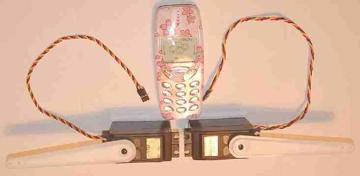
WING ACTUATORS Jumbo HiTec Sail Servos - HS-715BB - 14.5kg/cm
The giant (by radio control standards) servos above are shown adjacent to a Nokia 3310 mobile phone to give an idea of the scale. The arms are 12cm long - perfect for lifting a bank of solar panels (wing).
Our local Model Aerodrome in Seaside Road, Eastbourne, supplied these beauties, taking the trouble to source one unit from afar - not the kind of thing you are asked for every day. Thanks to Dave and Steve for helping us out of a tough spot. The Model Aerodrome were also able to match a reduction gearbox shown elsewhere on this site under catamaran model drive-train.
CONTROL BOARDS
On
this page we also look at two electronic design solutions for control of
our wing angle. One is an analogue comparator based circuit, the other a
digital computer chip based circuit. They both do the same thing, but
with different features.
SOLAR TRACKING THEORY & PRACTICAL EXAMPLES SOLAR WING PANEL ACTUATORS & CONTROL KITS ELECTRONIC COMPUTER CHIP SUN TRACKING SOLUTION MPPT ELECTRONIC SUN TRACKER PCB DEVELOPMENT
LM339 COMPARATOR BASED SUN TRACKER
There are many ways of arranging for an array of panels to track the sun. The description below is for a DIY control board that seems to work quite well. But there are dozens of designs from enthusiastic roboteers. See the links below.
LM339 BASED SUN TRACKER DIY COMPONENT LIST
dU1/U2 - LM339 quad
comparator
Circuit diagram for the LM339 quad comparator based sun tracker
Template to drill and etch your own PCB (37mm x 37mm)
The LED arrangement in the LM339 circuit below uses two rows of three LEDs with each LED connected in parallel, the two rows are connected in parallel but reversed polarity. The sensor array is made with three west LEDs and three east LEDs. A 1meg resistor and a 10n ceramic capacitor (103z) are also in parallel with the sensor. The sensor LEDs provide input voltage for two comparators on the LM339 chip with the variable resistor R2 providing a "dead zone" or sensitivity adjustment. Each comparator output is fed into a transistor Darlington pair which in turn drives the DC motor. The rail voltages are provided by two batteries connected in series with the center tap providing the ground reference.
The developers at Green Watts have tested this circuit with 2 single cell lithium-ion batteries providing +/- 4.2 volts and two 12 volt lead batteries, the LM339 is rated for input voltages from +/- 2 volts to +/- 18 volts.
MMT SCIENTIFIC KIT
This special COMPUTER CHIP CONTROLLED SOLAR TRACKER CIRCUIT KIT (Catalog #ST2-HD-PIX) from MTM Scientific is a new product they are making available on a limited basis for advanced electronic hobbyists. Identical in function to their other Solar Tracker Kits, this kit contains all the electrical components for building the circuit (shown above) to automatically find and follow the sun across the sky.
Just like their other kits, this tracker circuit finds the sun at dawn, follows the sun during the day, and resets to home at nightfall for the next day. This kit is ideal for driving a single axis solar tracker with a 12 VDC gear motor or linear actuator that they don't provide. Also included, but not shown, are the same 2 photocell sensors, 2 limit switches and 20+ page booklet they include with all their Solar Tracker Kits.
So what is different about this kit? This new version of our Solar Tracker Kit is controlled by a PIC micro-controller running a computer program written in PICAXE BASIC. Much more information about the Picaxe family of micro-controllers is available at Phil Anderson's website (www.phanderson.com). The Picaxe Chip can be reprogrammed using the serial port of your computer using the Picaxe Development Platform Software (Download and Installation required). Obviously that would be a project for advanced hobbyists capable of reading and writing computer line code and reading circuit diagrams. Note: We provide the Picaxe chip already programmed for this kit.
PIC computer chip based sun tracker kit
Yes, two new features were added in the software code:
1) The Tracker has a FAST/SLOW update rate limit which only allows position changes once every 1 minute, or once every 10 minutes. This feature reduces wear and tear on the mechanical and electrical hardware.
2) The Tracker has a software feature which requires all motion updates to be of 1/10 second duration or more, to reduce 'jogging' and 'hunting'... essentially software controlled hysteresis.
What are some ideas for advanced applications? Advanced hobbyists might consider writing code to do optimized sunlight threshold detection, smart parking, historical data analysis, bright cloud ignore, heliostat applications and really... just about anything imaginable. MMT are interested to know more about your code improvements... a key reason they are offering this kit! We're sure that MMT would like the wing application on the SolarNavigator.
Please note: This circuit kit is for advanced electronic hobbyists interested in experimenting with PIC computer control of Solar Trackers. This kit will control a Solar Tracker after assembly, similar to their standard kits. However modifying the computer code will require advanced skills such as line coding, serial port communication and self-directed project development. This kit includes a supplementary handout with special circuit diagram, additional details and a listing of the PICAXE BASIC source code.
HYDRAULIC v MECHANICALLY GEARED SERVOS
1. HYDRAULIC RAM
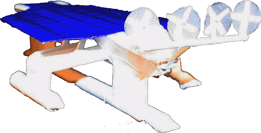
The next question is what is the best mechanical design to move the wing panels? Hydraulic rams are relatively cheap and come in almost any shape and size. So they are the obvious first choice for simplicity, coupled to an electric pump. But, a hydraulic ram's linear action is restrictive, if the movement of the wings is 230 degrees (as in this case - see diagram above), a simple ram/lever arrangement is not going to work. A chain and wheel system to convert the simple linear ram movement into a rotary one is an option we might consider - but needs an idler pulley wheel - and that means more bearings: bearings mean losses in efficiency.
We need efficiency in the movement, with 16,800 readings giving us a likely 5,600 movements to track the sun over 280 days. Multiply the expected 5,600 movements x motor wattage x time and that gives us the total energy required over the voyage for sun tracking, which in turn allows us to estimate the net increase in collected energy of between 12-18%. A worthwhile increase.
2. SERVO GEAR MOTOR
The design of this robot ship must exceed the life of the expedition to encompass long term scientific oceanographic surveys. Such surveys might last for 12 months or more. The design of the ship must therefore be for trouble free operation of at least five years, but preferably 10 years or more - without more than routine servicing in port. Thus, we are looking at a movement capable of 75,000 incremental adjustments (as 7,300 full open-close actions).
The picture above is of the innovative Dunkermotor Bifurcated Wormetary drive that combines a right angle worm gear to turn the corner with a pair of efficient planetary gearboxes for a total reduction ratio of 529:1. Overall reductions up to 50,000:1 can be achieved with the Wormetary configuration. The gearboxes share the load through beefy 25mm output shafts and each side is rated for a continuous output torque of 160 N-m (1,416 in-lbs) and peak outputs of 320 N-m (2,832 in-lbs). For a solar tracking application, the Wormetary gearing is non-backdrivable, which is a benefit in the presence of wind loading.
In this example the 60 volt brushless motor shown above, of 530 Watts (0.71 hp) x 2 wings [x 560 x 10mins / 60] = 99Kw/hrs.
From the graph below we can assume a daily energy collection average of 50kw/hrs/day x 280 days, to equal = 14,000Kw/hrs. That is without solar tracking. Now add a 12% increase = 1680Kw/hrs and take away the 99Kw/hrs used by the tracking motors, gives us a 1,590Kw/hrs increase over the 280 day expedition. If the suntracker system yielded an 18% increase in total collection, that would be 2,421 extra kilowatt/hours. Either example shows a significant performance improvement, provided that the additional weight of the system does not add significantly to the drag of this autonomous vessel.
A GRAPH USED AS A DEVELOPMENT TOOL TO ESTIMATE SOLAR PANEL AREA FOR A GIVEN PERFORMANCE
An off the shelf single axis sensor/motor sun tracker sold as an educational toy
SUN TRACKER LINKS
http://www.solarmade.com/SolarPanels http://solartracker.greenwatts.info/solar_tracker_LM339_schematic.htm http://hackedgadgets.com/2008/05/23/sun-tracking-solar-panel-system http://www.redrok.com/electron.htm#led3 http://www.solarmade.com/Educational http://mad-science.wonderhowto.com/how to make a more efficient diy sun tracker http://www.mtmscientific.com/stpicaxe.html PIC computer chip based kit for $78 http://ecorenovator.org/forum/solar-power/875-solar-tracker-project-13.html http://www.ecnmag.com/product-releases/sun tracker gearmotors-continuous-torque http://mechanical.poly.edu/
The ultimate Robot Boat. Solarnavigator uses an advanced SWASSH hull as the platform to mount the world's first autonomous circumnavigation. A successful expedition could pave the way for improved safety at sea.
|
||||||||||||||||||||||||||||||||||||||||||||||||||||||||||||||||||||||||||||||||||||||||||||||||||||||||||||||||||||||||||||||||||||||||||||||||||||||||||||||||||||||||||||||||||||||||||||||||||||||||||||||||||||||||||||||||||||||||||||||||||||||||||||||||||||||||||||||||||||||||||||||||||||||||||||||||||||||||||||||||||||||||||||||||||||||||||||||||||||||||||||||||||||||||||||||||||||||||||||||||||||||||||||||||||||||||||||||||||||||||||||||||||||||||||||||||||||||||||||||||||||||||||||||||||||||||||||||||||||||||||||||||||||||||||||||||||||||||||||||||||||||||||||||||
|
This website is copyright © 1991- 2013 Electrick Publications. All rights reserved. The bird logo and names Solar Navigator and Blueplanet Ecostar are trademarks ™. The Blueplanet vehicle configuration is registered ®. All other trademarks hereby acknowledged and please note that this project should not be confused with the Australian: 'World Solar Challenge'™which is a superb road vehicle endurance race from Darwin to Adelaide. Max Energy Limited is an educational charity working hard to promote world peace.
|
||||||||||||||||||||||||||||||||||||||||||||||||||||||||||||||||||||||||||||||||||||||||||||||||||||||||||||||||||||||||||||||||||||||||||||||||||||||||||||||||||||||||||||||||||||||||||||||||||||||||||||||||||||||||||||||||||||||||||||||||||||||||||||||||||||||||||||||||||||||||||||||||||||||||||||||||||||||||||||||||||||||||||||||||||||||||||||||||||||||||||||||||||||||||||||||||||||||||||||||||||||||||||||||||||||||||||||||||||||||||||||||||||||||||||||||||||||||||||||||||||||||||||||||||||||||||||||||||||||||||||||||||||||||||||||||||||||||||||||||||||||||||||||||||
|
AUTOMOTIVE | BLUEPLANET BE3 | ELECTRIC CARS | ELECTRIC CYCLES | SOLAR CARS | SOLARNAVIGATOR |
||||||||||||||||||||||||||||||||||||||||||||||||||||||||||||||||||||||||||||||||||||||||||||||||||||||||||||||||||||||||||||||||||||||||||||||||||||||||||||||||||||||||||||||||||||||||||||||||||||||||||||||||||||||||||||||||||||||||||||||||||||||||||||||||||||||||||||||||||||||||||||||||||||||||||||||||||||||||||||||||||||||||||||||||||||||||||||||||||||||||||||||||||||||||||||||||||||||||||||||||||||||||||||||||||||||||||||||||||||||||||||||||||||||||||||||||||||||||||||||||||||||||||||||||||||||||||||||||||||||||||||||||||||||||||||||||||||||||||||||||||||||||||||||||

